1.
Introduction
DFTAdvisor is a utility
that allows you to insert scan circuitry into your design. It follows one of
two basic strategies: The first is full scan. Full scan converts every flip
flop and latch into scanable flip flops, which allows the use of combinational test
pattern generation. . After inserting the scan circuitry, you can then generate
test vectors for your design by using Fastscan The other strategy is partial
scan. With partial scan you only insert scan circuitry in some of the memory
devices. In this tutorial we are using a 4 bit counter written in verilog
(ud_counter) as our illustrative example design.
2. Invoking DFTAdvisor
- To invoke DFTAdvisor on your
ud_counter.v you must first set the mentor graphics working directory to
the current directory that has your ud_counter.v file. The atglib file
should be in the same directory that your edif file is in.
- To start DFTAdvisor, you need
to enter the command in the format:
dftadvisor ud_counter.v
-verilog -lib atglib
After
invoking DFTAdvisor, the DFTAdvisor Control Panel and the command line will
appear as shown in Figure 1.

Figure 1 DFTAdvisor Control Panel
- DFTAdvisor defines
"clocks" as any signal that can change the state of a scan
element (or a memory element) that we want DFTAdvisor to convert to scan.
In the DFTAdvisor Control Panel , click on the Clocks, select Manually
Define, click on the Primary Input Clocks drop-down list,
select the /clk input from the list, select the ‘0’ as the Off-state,
click on the Add button as shown in Figure 2. , and click OK.

Figure 2 Setup Circuit Clocks
The equivalent command line will be :
SETUP>
add clocks 0 CLK
- To check the setup environment
of DFTAdvisor, type report environment in the command line.
SETUP>
report environment
The
setup environment will tell you what kind of setup you have for your
environment.
- To change system mode from
SETUP to DFT, click Done With Setup in the DFTAdvisor Control
Panel. The System Mode is DFT as shown in Figure 3. The DFTAdvisor
performs learning analysis on the circuit and reports information that it
finds. The DFTAdvisor then identifies the memory elements in the design
and performs scannability checks on them. It then performs clock rules
checking on the identified clocks.

Figure 3 DFTAdvisor Control Panel
The equivalent command line will be :
SETUP> set system mode dft
- This step allows you to specify
whether to use full scan or partial scan. If you wish to use full scan,
click on the Setup Identification, then select the Full Scan
option, and click OK. If you wish to use partial scan, click on the
Setup Identification, then select the Partial Scan option,
and click OK.
The equivalent command line for setting the
full scan will be :
DFT> setup scan identification full_scan
The equivalent command line for setting the
partial scan will be :
DFT> setup scan identification sequential
atpg –internal –percent 100 –controllability 100 –observability 100
–min_detection 0.01 –backtrack 30 –cycle 16 –time 100
- To Run scan identification,
click on the Run Identification ,and click on the Run With
Existing Settings button.
The equivalent command line will be :
DFT> run
Click on Dismiss to close the DFTAdvisor Identification Run Statistics
window.
- To synthesize the scan
circuitry, click on the Setup/Run Test Synthesis. From the Setup/Run
Test Synthesis dialog box, you have the option to change the existing
setup for scan circuitry, test points, test logic, and input/output
buffers for test pins. In this case, you will use the default settings so
click on OK, click on the Run With Existing Settings button,
and click OK.
The equivalent command line will be :
DFT> insert test logic –scan on
–test_point on -ram on
Note: Once the netlist is changed ( because of the
scan insertion), the flattened simulation model of the design that is used by
DFTAdvisor is no longer valid. That is what is meant by “Flattened model has
been freed.” You can ignore this warning.
- To write the new, scan-inserted
version of the netlist, click on the Save Results button. From the Save
Results dialog box, click on the Save the New Netlist option,
enter ud_counter_fs.v (for Verilog format) or ud_counter_fs.edif (for EDIF
format) in the Pathname field, and click on the Overwrite Existing File
option as shown in Figure 4.

Figure 4 Save the New Netlist
The equivalent command line will be :
write netlist {design_name} -verilog -replace. In this
tutorial, we will append a _fs to the design name for full scan and _ps for
partial scan.
For this design, if your design is
full scan enter:
DFT> write netlist ud_counter_fs.v -verilog -replace or
DFT> write netlist ud_counter_fs.edif -edif -replace
If your design is partial scan
enter:
DFT> write netlist ud_counter_ps.v -verilog -replace or
DFT> write netlist ud_counter_ps.edif -edif -replace
- To write a dofile and test
procedure file for the scan-inserted design, click on the Save Results
button, select the Save Setup Files for ATPG option and enter
ud_counter_fs as the Basename, and click on the Overwrite
Existing File option as shown in Figure 5.
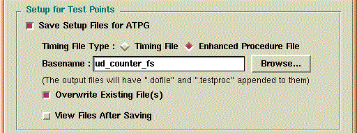
Figure 5 Save Setup Files for ATPG
It
will create two files. If your design is full scan they will be
ud_counter_fs.dofile and ud_counter_fs.testproc. If they are partial scan they
will be ud_counter_ps.dofile and ud_counter_ps.testproc.
The equivalent command line will be :
DFT> write atpg setup {design_name}
-replace
If
you are creating a full scan design, type:
DFT> write atpg setup ud_counter_fs -replace
If
you are creating a partial scan design, type:
DFT> write atpg setup ud_counter_ps -replace
The
dofile contains commands that can be used in Fastscan or Flextest to identify
the scan circuitry of your design, so they can generate test vectors. Here are
the contents of the dofile
ud_counter_fs.dofile:
//
// Generated by DFTAdvisor at Thu Aug 1 13:13:13 2002
//
add scan groups grp1 ud_counter_fs.testproc
add scan chains chain1 grp1 scan_in1 scan_out1
add clocks 0 clk
The following are the contents of the file ud_counter_fs.testproc:
//
// Generated by DFTAdvisor at Thu Aug 1 13:13:13 2002
//
set time scale 1.000000 ns ;
timeplate gen_tp1 =
force_pi 0 ;
measure_po 10 ;
pulse clk 20 10;
period 40 ;
end;
procedure shift =
scan_group grp1 ;
timeplate gen_tp1 ;
cycle =
force_sci ;
measure_sco ;
pulse clk ;
end;
end;
procedure load_unload =
scan_group grp1 ;
timeplate gen_tp1 ;
cycle =
force clk 0 ;
force scan_en 1 ;
end ;
apply shift 4;
end;
The testproc file contains the testing procedures used
by Fastscan or Flextest shift in the test vectors generated in those utilities.
- To terminate the session, click
on the Exit button.
The equivalent command line will be :
DFT>
exit
click here to go
back to Index: