The 8253 Timer contains 3 independent channels. Each channel consists of a 16-bit downcounter with a CLOCK input, a GATE input for enabling/triggering the count, and a counter output (OUT), a 16-bit COUNT register for holding the count value, and a CONTROL register for controlling the operation of the counter and the loading/reading of the COUNT register. Each channel may count in one of six modes (interrupt on terminal count, hardware retriggerable one-shot, rate generator, square wave generator, software triggered strobe, and hardware triggered strobe) and may count in BCD or binary. The output is formed by copying the contents of the channel's COUNT register to the channel's counter and starting the downcount. Depending on the mode selected, the GATE input may act as an enable input, or as a trigger to start the downcount; similarly, the downcounter may automatically reload the COUNT and repeat, or require a reload/retrigger (one-shot operation). Consult the Intel 8253-5 Programmable Interval Timer data sheet for more details.
The CONTROL register of a channel is loaded by writing a control byte to I/O port 43h. The interpretation of the control byte is shown in Table 1; note that bits 7 and 6 determine which channel is affected.
Table 1. Interpretation of the Timer Control Byte
|
Bits 7,6: |
Channel ID (11 is illegal) |
||||
|
Bits 5,4: |
Read/load mode for two-byte count value:
|
||||
|
Bits 3,2,1: |
Count mode selection (000 to 101) |
||||
|
Bit 0: |
0/1: Count in binary/BCD |
The 16-bit COUNT registers of channels 0, 1, and 2 are located at I/O ports 40h, 41h, and 43h, resp. Each COUNT register must be loaded according to the mode selected in the CONTROL byte for that channel; single-byte loads leave the other byte 0. The COUNT register may be read "on the fly" by latching the current count from the downcounter into the COUNT register while the downcounter continues counting.
In the PC all three channels use a 1.19318 MHz signal as clock input. GATE0 and GATE1 are permanently tied to 1, so the outputs of Channels 0 and 1 are continuous. The channels are programmed during the BIOS power-up initialization sequence as follows:
The CONTROL byte for Channel 0 is 00110110b Channel 0, 2-byte count value, mode 3 (continuous symmetrical square wave), count in binary. The COUNT value for Channel 0 is 0000h, i.e., 65536 counts, so the frequency of OUT0 is 1.1931817 Mhz/65536 ≈ 18.2 Hz. Channel 0's output is connected to the IRQ0 Interrupt Request line of the 8259 Interrupt Controller; hence an interrupt 08h will occur at a 18.2 Hz rate, or once every 55 msec. The interrupt 08h handler maintains the PC's time-of-day clock and performs other internal timing functions. To simplify the use of the timer interrupt for user applications (and to minimize interactions with the internal timing functions), the interrupt 08h handler issues a software interrupt 1Ch which is vectored during initialization to the "default interrupt handler" (an IRET).
The CONTROL byte for Channel 1 is 01010100b Channel 1, 1-byte (LSB) count value, mode 2 (rate generator), count in binary. The COUNT value for Channel 1 is (00)12h = 18, so the frequency of OUT1 is 1.1931817 Mhz/18 ≈ 66 kHz. Channel 1 controls the refresh timing of the memory.
The CONTROL byte for Channel 2 is 10110110b Channel 2, 2-byte count value, mode 3 (symmetrical square wave, continuous provided OUT2 = 1), count in binary. The COUNT value for Channel 2 is 0533h = 1331, so the frequency of OUT2 is 1.1931817 MHz/1331 ≈ 896 Hz. Channel 2 is used to produce a beep from the built-in speaker. More details on controlling the speaker are given below.
The PC has an internal speaker which is capable of generating beeps of different frequencies. You control the speaker by providing a frequency number which determines the pitch of the beep, then turning the speaker on for the duration of the beep.
The frequency number you provide is actually a counter value. The PC uses it to determine how long to wait between sending pulses to the speaker. A smaller frequency number will cause the pulses to be sent quicker, resulting in a higher pitch. The PC uses a base rate of 1,193,180 Hz (this frequency is generated by an oscillator chip). The frequency number tells the PC how many of these cycles to wait before sending another pulse. Thus, you can calculate the frequency number required to generate a specific frequency by the following formula:
The frequency number is a word value, so it can take values between 0 and 65,535 inclusive. This means you can generate any frequency between 18.21 Hz (frequency number = 65,535) and 1,193,180 Hz (frequency number = 1).
Following is a diagram of the hardware for driving the built-in speaker. OUT2 is the output of Channel 2 of the 8253-5 timer chip, GATE2 (= bit 1 of port 61h) is the enable/trigger control for the Channel 2 counter, and SPEAKER DATA (= bit 0 of port 61h) is a line that may be used independently to modulate the output waveform, e.g., to control the speaker volume.
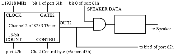
The count and load modes selected for Channel 2 during BIOS initialization are probably the best to use for tone production. In Mode 3, the counter output is a continuous symmetrical square wave as long as the GATE line of the channel is enabled; the other modes either produce outputs that are too asymmetrical or require retriggering for each count cycle.
The frequency count is loaded into the Channel 2 COUNT register at I/O port 42h. GATE2 (bit 1 of I/O port 61h) must be set to 1 to get an output on OUT2; the SPEAKER DATA line (bit 0 of I/O port 61h) must also be set to 1 to produce a tone. Note that the remaining bits of port 61h must not be changed since they control RAM enable, keyboard clock, etc. To silence the speaker, bits 1 or 0 of port 61h are set to 0 (without disturbing the remaining bits of port 61h).
You can communicate with the speaker controller using IN and OUT instructions. The following lists the steps in generating a beep:
Send the value 182 to port 43h. This sets up the speaker.
Send the frequency number to port 42h. Since this is an 8-bit port, you must use two OUT instructions to do this. Send the least significant byte first, then the most significant byte.
To start the beep, bits 1 and 0 of port 61h must be set to 1. Since the other bits of port 61h have other uses, they must not be modified. Therefore, you must use an IN instruction first to get the value from the port, then do an OR to set the two bits, then use an OUT instruction to send the new value to the port.
Pause for the duration of the beep.
Turn off the beep by resetting bits 1 and 0 of port 61h to 0. Remember that since the other bits of this port must not be modified, you must read the value, set just bits 1 and 0 to 0, then output the new value.
Another way to control the length of beeps is to use the timer interrupt. This gives you better control over the duration of the note and it also allows your program to perform other tasks while the note is playing.
The following table lists frequencies and frequency numbers for the three octaves around middle C on a piano keyboard.
| Note | Frequency | Frequency # |
|---|---|---|
| C | 130.81 | 9121 |
| C# | 138.59 | 8609 |
| D | 146.83 | 8126 |
| D# | 155.56 | 7670 |
| E | 164.81 | 7239 |
| F | 174.61 | 6833 |
| F# | 185.00 | 6449 |
| G | 196.00 | 6087 |
| G# | 207.65 | 5746 |
| A | 220.00 | 5423 |
| A# | 233.08 | 5119 |
| B | 246.94 | 4831 |
| Middle C | 261.63 | 4560 |
| C# | 277.18 | 4304 |
| D | 293.66 | 4063 |
| D# | 311.13 | 3834 |
| E | 329.63 | 3619 |
| F | 349.23 | 3416 |
| F# | 369.99 | 3224 |
| G | 391.00 | 3043 |
| G# | 415.30 | 2873 |
| A | 440.00 | 2711 |
| A# | 466.16 | 2559 |
| B | 493.88 | 2415 |
| C | 523.25 | 2280 |
| C# | 554.37 | 2152 |
| D | 587.33 | 2031 |
| D# | 622.25 | 1917 |
| E | 659.26 | 1809 |
| F | 698.46 | 1715 |
| F# | 739.99 | 1612 |
| G | 783.99 | 1521 |
| G# | 830.61 | 1436 |
| A | 880.00 | 1355 |
| A# | 923.33 | 1292 |
| B | 987.77 | 1207 |
| C | 1046.50 | 1140 |